
I wanted to add automation to the lighting in my house. Normally this would involve using DIN rail mounted X10 lamp modules, with star wired lighting circuits (i.e. all lights are individually cabled back to a central control panel), but as I wanted to retro-fit to my existing wiring this was not practical. There are now 'micro-modules' available, which are inline X10 modules designed to fit in the back of an existing switch back-box. Unfortunately they are about 60 UK pounds each - ouch!
Anyway, I managed to pick up several LM12U plug-in X10 lamp modules very cheap (thanks Homebase!), so I decided to modify them to inline modules which can be hidden in the ceiling void above the light fittings. However, it was essential for me that I could retain manual control of the lights - that is, when you switch the wall switch ON, the light turns ON! The problem is that the LM12U modules do not switch the lamp on until they receive an X10 ON command. To fix this, I modified the local control current sensing circuit by adding an R/C delay that triggers the local control sensing at power on. This is not perfect though - it takes the microcontroller approximately 1 second to initialise, and only then will it respond to the local control sense input. The result of this is that the lamp turns on after approximately 1.5 seconds of switching the power on. The effect is pretty similar to switching on a flourescent light, and I will have to live with that. I maybe could have got around this problem by building a circuit to trigger the triac immediately, before handing over control to the microcontroller, but I wanted to keep things as simple as possible.
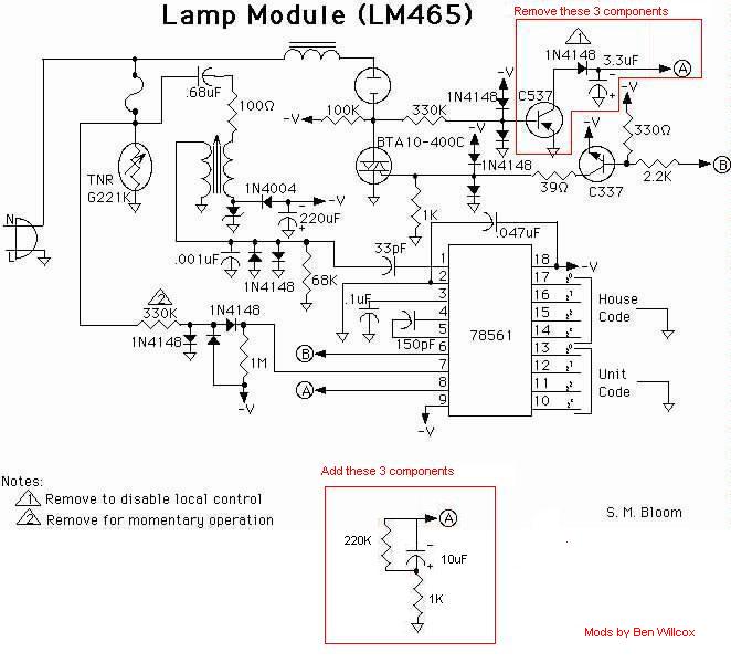
Click here for a circuit schematic (Thanks to Steve Bloom for the original.) Actually the US version, but the bit we're interested in is the same.
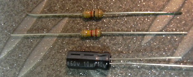 |
You will need 3 components:
|
|
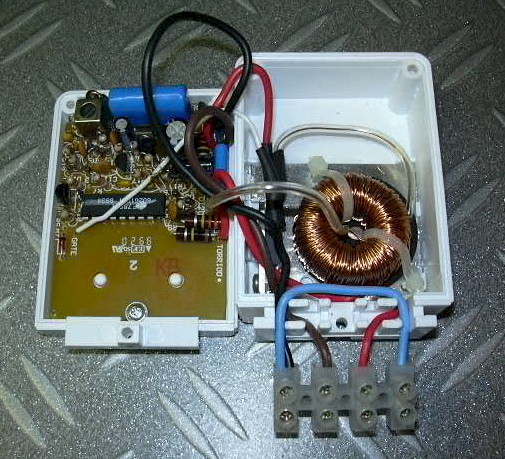
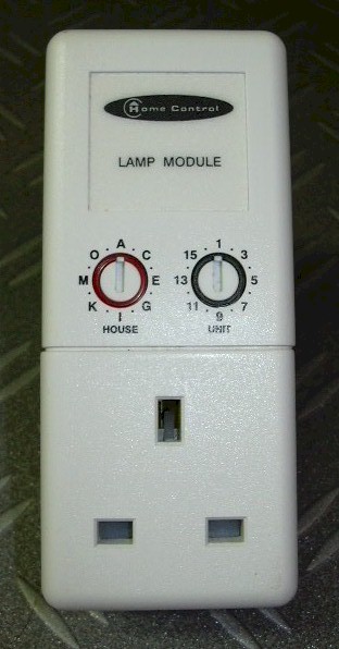
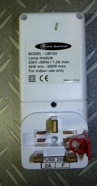
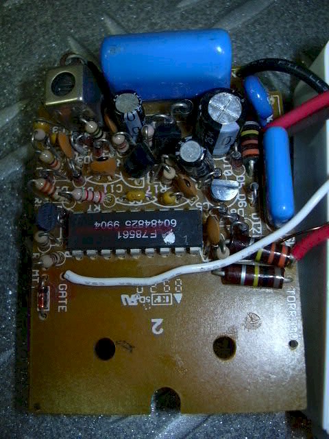
Heres the module, front and back. Undo the 4 screws, one of them is hidden under the fuse holder. Now you can prise off the covers and see that the module is in two sections.I'm guessing the European modules electronics are identical, with just a different bottom section depending on the plug and socket configuration. If you can confirm this please send me an Email! Unscrew the PCB and detatch from the front cover. |
|
|
|
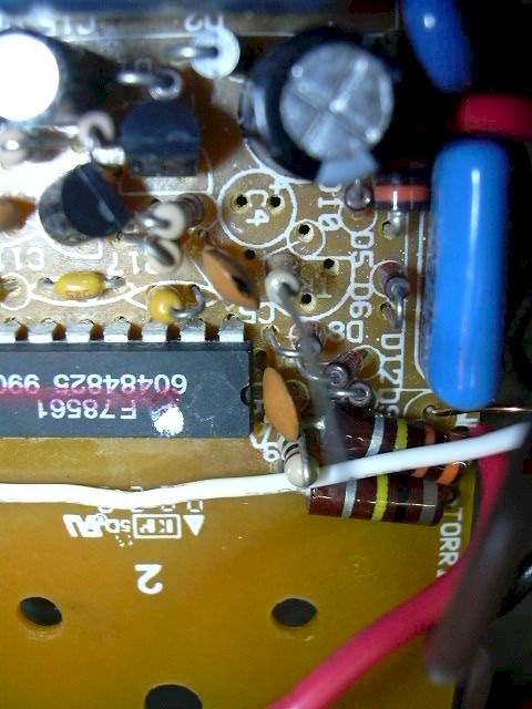
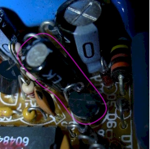
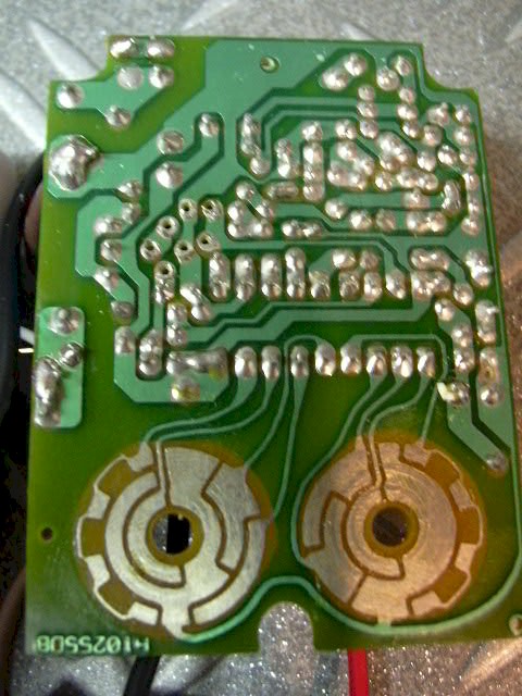
You now need to remove three components, a 3.3uF electrolytic cap, diode and transistor. The right-hand picture shows the rear of the PCB after removal - you can see the 6 holes where the components used to be. |
|
|
|
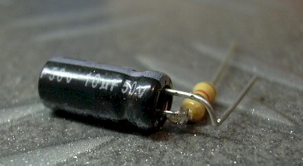
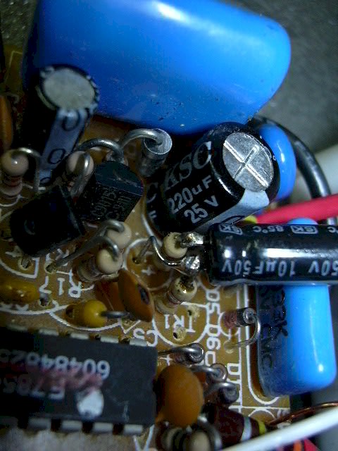
Form the 10uF cap and 1K resistor as shown (resistor connects to the +ve capacitor lead). Then solder the 220K resistor into the left-hand transistor hole. Finally, insert the capacitor/resistor, and solder the top leg of the 220K resistor to the -ve side of the cap. The 10uF capacitor has to sit up about 45 degrees due to the blue capacitor on the right. |
   |
|
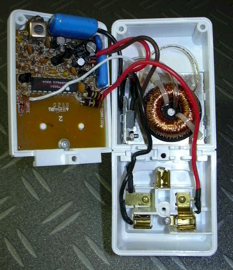
If you want to keep the module as a plug in unit, you are done. If you want an inline module, you can desolder or cut the wires as they go to the plug/socket and add screw terminals. I like to add a 4 terminal block with a neutral loop for ease of connection to the light fitting. This gives me the following connections (left to right):
|
  |
Above the ceiling rose or light fitting you need to make a hole big enough for the module to fit into. Then connect the light fitting to the Load terminals on the module, and the power (where the light fitting used to connect to) to the Supply terminals on the module. You now can control your lights normally (with a 1.5 second ON delay!) or with X10 (when the light switch is ON, obviously).
![]()
![]()