My ICQ
Status:

 |
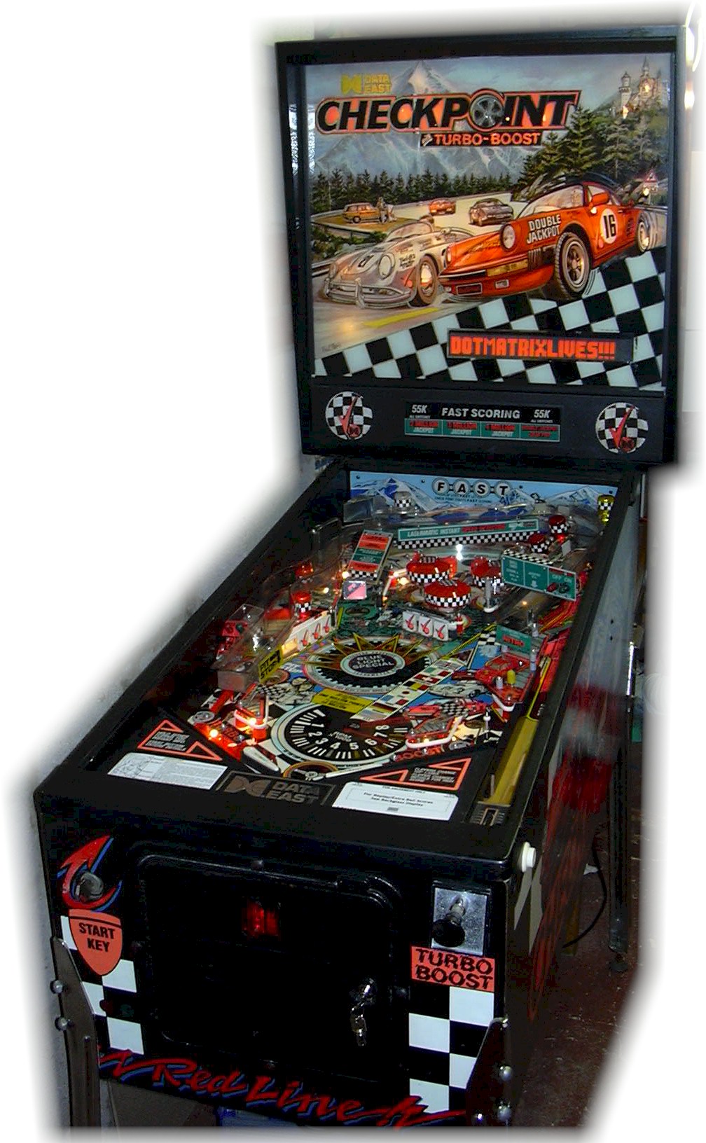
Its been many years since I bought my first pinball machine, a 1985 Premier/Gottlieb Rock. It worked fine, just needed a little cleaning and new lamps - not bad for £70! Unfortunately I had to sell it due to lack of space, but I recently got the urge to get another machine. I found a 1991 Data East Checkpoint on Ebay fairly cheap, as it was faulty. I wanted a challenge so I got it! It was described as having been thoroughly cleaned and the lamps and rubbers replaced, but not being playable because the ball would straight away get stuck in the rear ball trough.There was also some mylar lifting. When it arrived I found a number of problems with it: |
 |
The flippers were very weak, and the auto-plunger coil would
fire with the flippers.
This was caused by a short circuit TIP36C transistor on the
PPB-1. I replaced this along with fuse F5 which had blown. This also
fixed the main problem the seller had reported where the ball would get
stuck in the rear ball trough because the vertical up-kicker didn't
work. It's alive, it's alive!
Auto-plunger kicker arm missing.
This game has both a manual and automatic plunger (the 'turbo-boost').
However, the arm that goes from the coil to auto-kick the ball was
missing, although the coil and pivot bracket were still in place. I
managed to find a replacement kicker-arm from Electrocoin
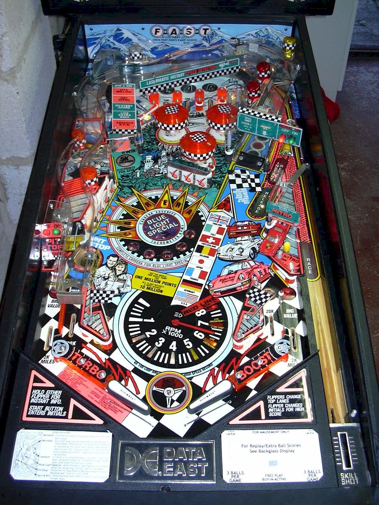
Aftersales. After fitting the arm, I found that it hit the
side of the cutout in the apron, so wouldn't hit the ball correctly:
.
After seeing a photo of another Checkpoint machine, I decided that the new kicker arm I had received was not the same as the original would have been, and the right-angle steel causing the obstruction was an improved strengthened design. So, to get it to work properly I had to widen the slot in the apron to allow the kicker arm through. I chopped about 5mm off with a junior hacksaw:
The next problem was that the manual plunger rod pushed the kicker-arm fully out when it was at rest. This meant that the auto-kicker could not fire unless I pulled the plunger out. It would appear that the outer plunger spring is too short, making the plunger stick in too far. A new spring will correct this, but I fudged it by clipping a plastic spacer between the plunger knob and the spring. It works for now!
CPU controlled lamps stopped working.
I traced this to a pulled wire from a plug/socket in the
bottom of the cabinet.
Some General Illumination lamps out on backbox.
Socket J5 on the PPB-1 was burnt. Apparantly this is a common
problem. After replacing the PCB mounted header and the plug everything
lit up!
Bottom cabinet speaker not working.
I found that the speaker itself was open-circuit. I found a
replacement from Maplin, order code GL13P. However,
on installing this new speaker I found that the volume from it was very
low. The Data East sound board uses 3 separate audio amplifiers (Left,
Right, Centre), and so I swapped the centre speaker onto one of the
other channels to determine whether the fault was with the new speaker
or the amplifier. The speaker worked fine on another channel, so the
fault had to be on the sound board. As I didn't yet have a schematic, I
tried swapping over the centre audio amplifier IC with one of the other
channels, but it made no difference. When I got the Checkpoint manual
from Pinball
Heaven, I managed to trace the problem to C13 on the sound
board. This looked like it had been leaking electrolyte, and after
replacing it the centre speaker sound was nice and loud like it should
be!
One drop target switch not working.
One lead of the diode had broken off due to vibration. This
worked fine once it had been resoldered.
Chequered flag drop target doesn't raise in play.
This target worked in test mode, but never raised while a
game was being played. It turned out to be simply that the switch
contacts needed adjusting, as they would never close.
Extra wire connected from 12V unregulated test point
to the Dot Matrix Display connector.
This was a bit of a hack job by a previous owner, which was
linking the 12V from the DMD into the 12V test point on the PSU board.
I removed this extra wire and measured the proper 12V DMD supply, but
there was nothing. Replacing the 12V regulator VR1 (7812) on the PSU
board restored the 12V supply.
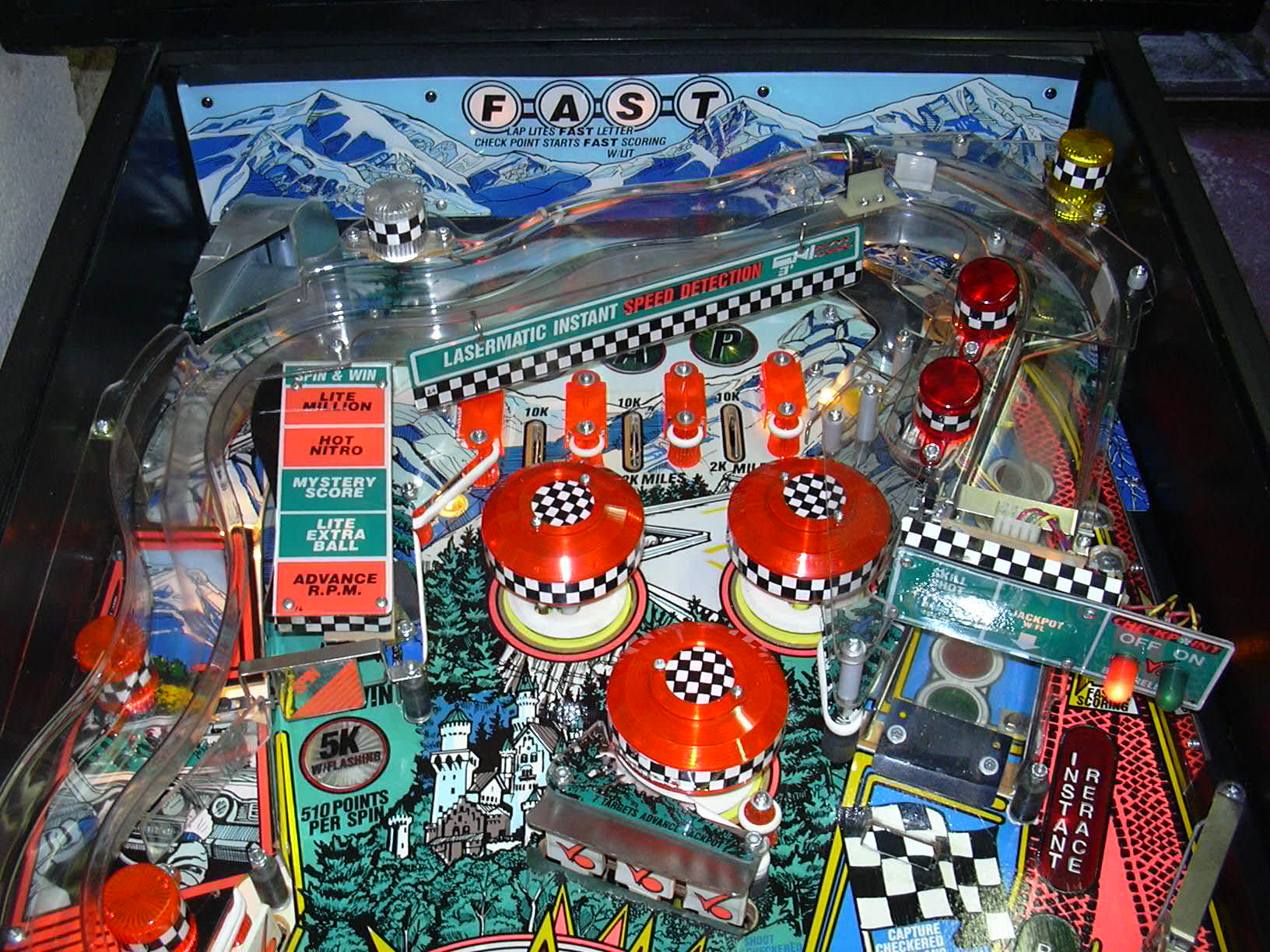
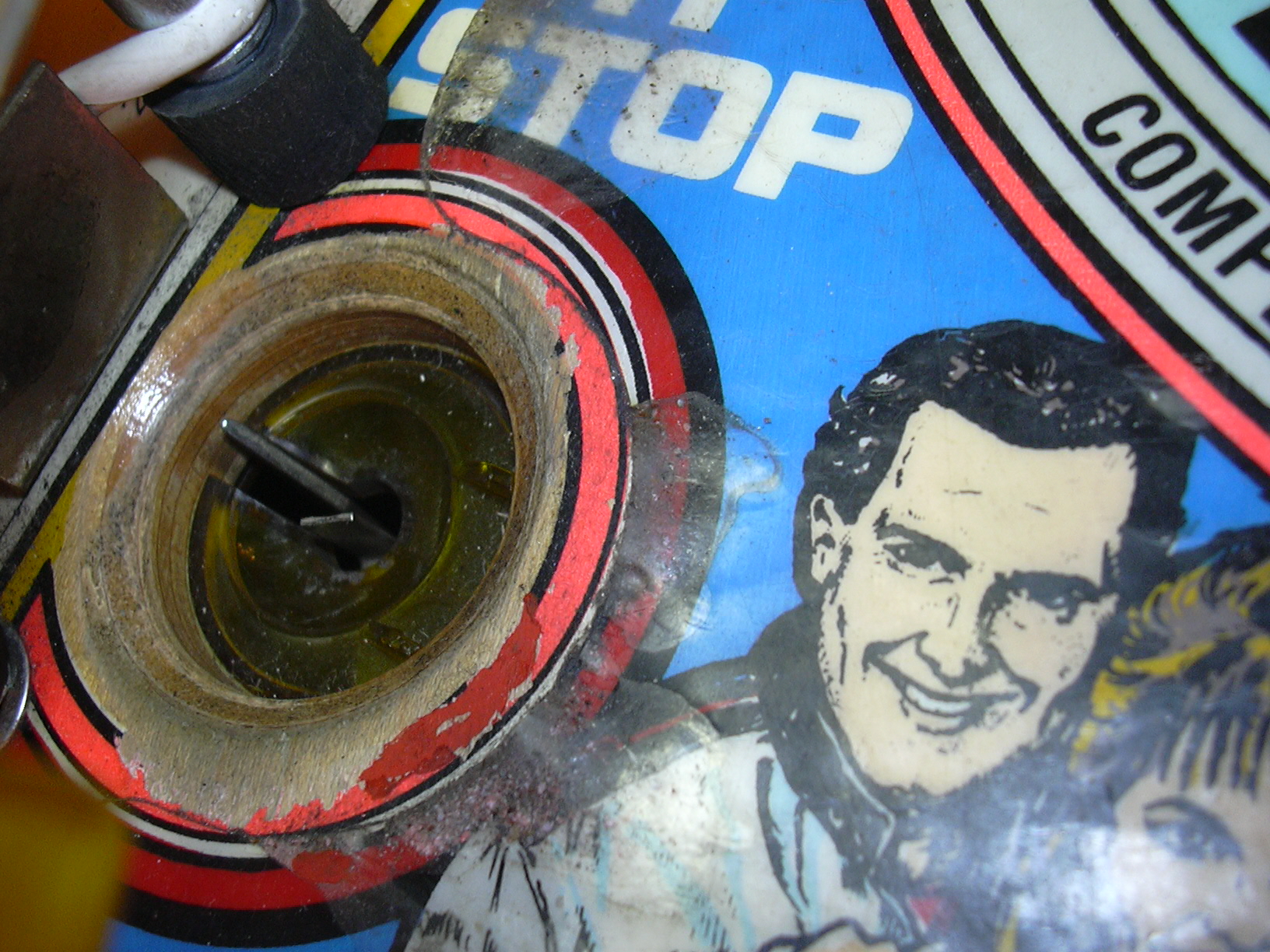
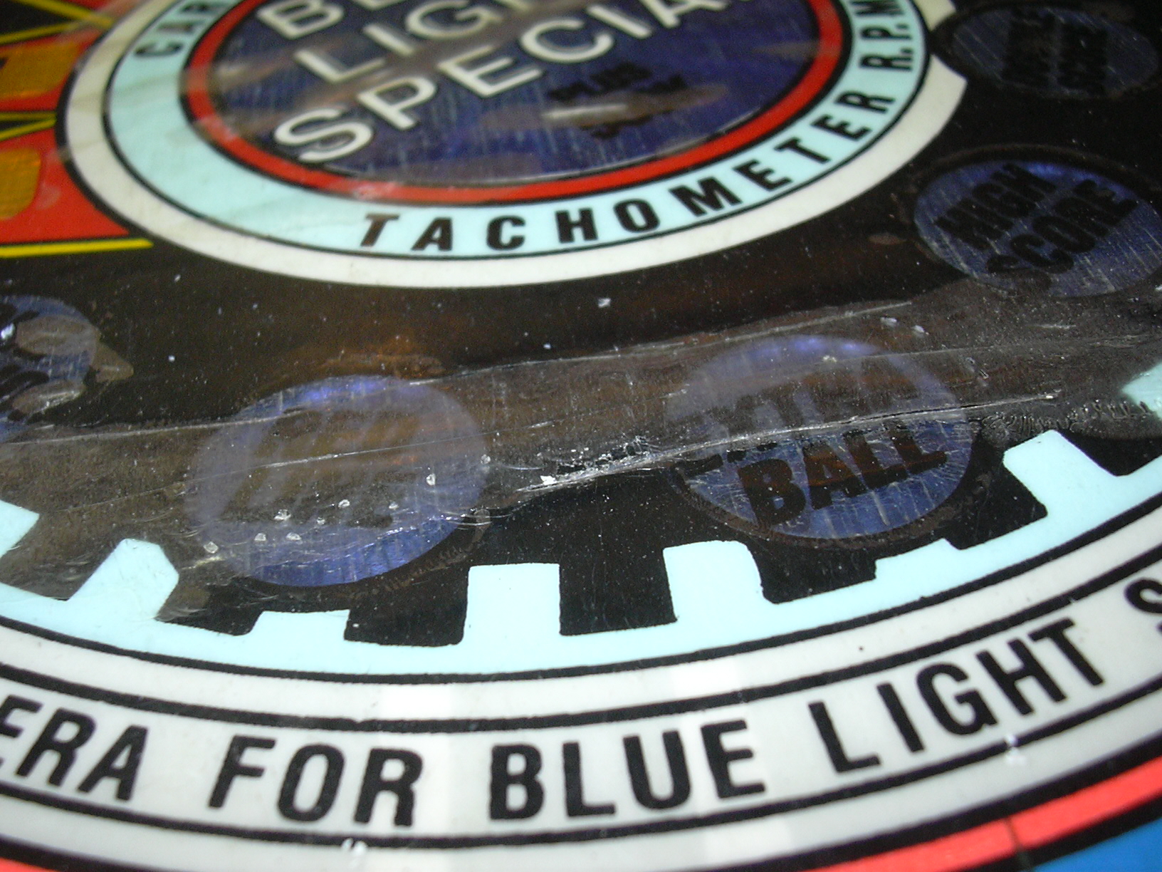
Removing the mylar.
The mylar was in quite bad condition, so there was no option
other than to remove it. Here are a couple of pics of the Pitstop and
Blue Light Special:
First task was to completely strip the playfield of all parts. I did this in sections, and kept each section's pieces in a separate plastic bag so I didn't get any bits mixed up. I took many digital pictures whilst doing this so I could work out how everything went back together! While taking the pieces off, I cleaned the plastics with Novus #2 plastic polish (from Pinball Heaven) and polished the metal parts using a metal polish. All the screws etc were very tarnished, but they came up really shiney with a bit of elbow grease!
|
There are a couple of methods for mylar removal, but I chose to use the method described in Mark's pinball pages. This referrs to a product called Goo-Gone, which is well known to pinball folks for removing glue such as the adhesive sticking down mylar. However, this is a US product and is not available in the UK. Looking around for an alternative, I found something called Sticky Stuff Remover (imaginative name!) in my local Focus DIY shop so I thought I'd give it a try. I think it's probably the same stuff as Goo-Gone, it has a citrus smell which apparantly the Goo-Gone has too. |
|
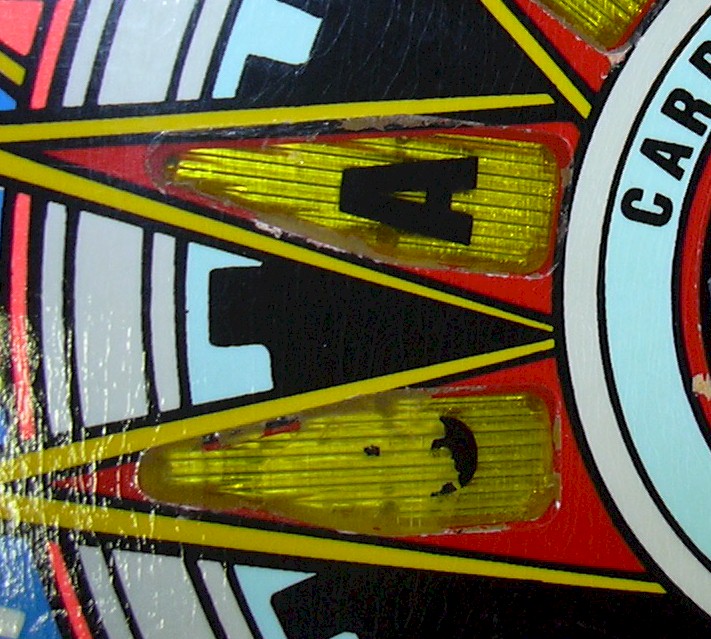
It worked pretty well, I used around 3/4 of a bottle to remove all the mylar and the glue from the playfield. There was some lifting around the lamp inserts, the worst part was on the C-A-R-R-E-R-A inserts on the Blue Light Special. The first part of the Mylar I removed pulled off almost all of the C - I nearly had a heart attack as I thought I was going to ruin the whole playfield! However, all of the other insert lettering was fine. There was some paint lifting around the edges of most of the inserts however, but I think this really is unavoidable. These edges can be touched up afterwards. You need to pull it off really slowly, I was pulling it around half a millimetre per second, and even slower if I was over a lamp insert. |
 |
| Here's a picture I took with half mylar, and half removed. The removed half is so shiny and clear, it looks like a brand new playfield! I cleaned the entire playfield with Novus #2 when I was finished, to get off any residue left behind. | 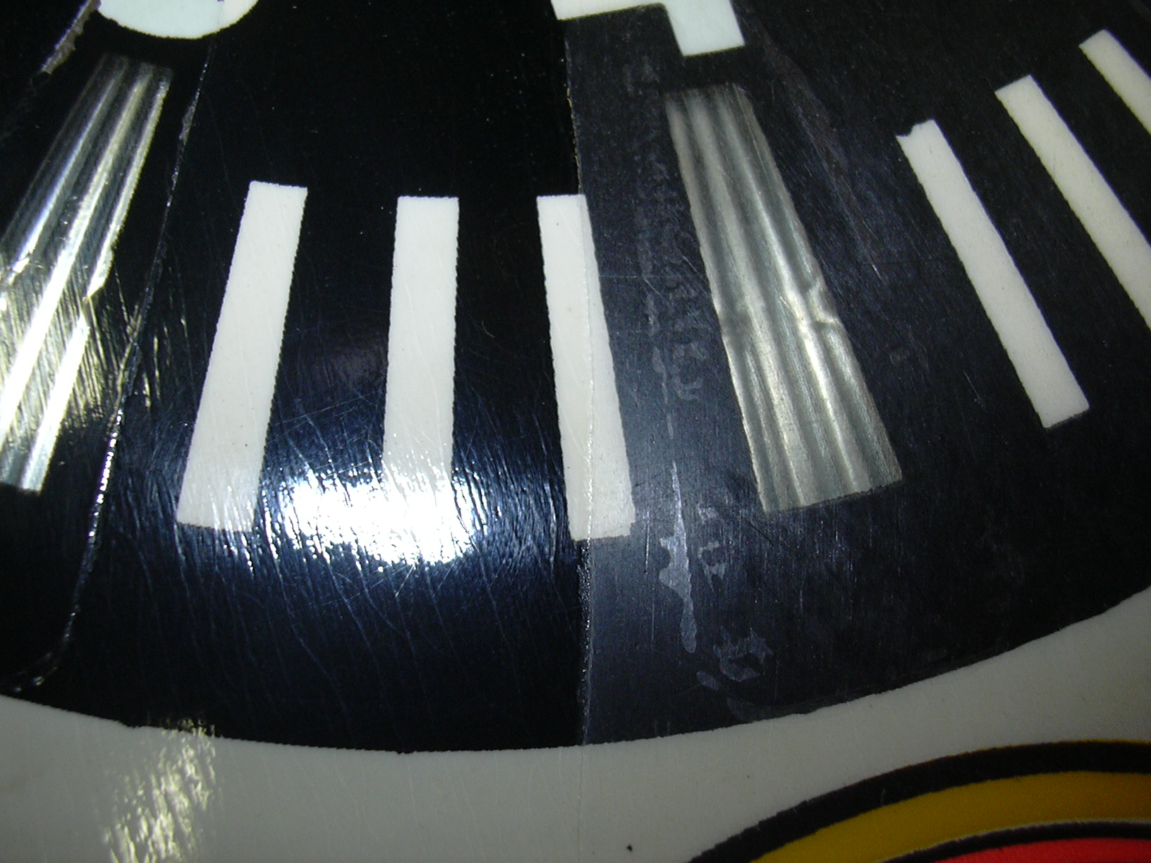 |
I found that Mark's advice and directions were pretty much spot-on. The only differences that I did was to not use a razor-blade ( I could peel up the mylar edges with a finger-nail), and I found that paper kitchen towels worked great to get the excess glue off the playfield! I also found it easier to puposely cut the mylar in places so it would tear, so I could do it in smaller sections. I cleaned up that section then moved on to the next.
| For touch-up paint I decided to use Acrylic paint. Some people advise the use of enamels as they are more hard-wearing, but acrylics are easier to work with, you can just wipe it off with a wet cloth if you make a mistake - very handy! I found a good range of colours at a local craft shop, these cost 85p for a small bottle. The red I chose was a perfect match for the red around the C-A-R-R-E-R-A inserts, although I had to mix a few for some of the other colours. I got a couple of very fine brushes for touching up the black lines etc. |
| Once I had touched up the light inserts and some other odd bits, I gave it 5 coats of Carnauba wax, which is the hardest wax available (and probably the most expensive, ouch!). I used One Grand Blitz Wax, and I got it from www.frost.co.uk which is the only place I could find it in the UK. (This is a US product). |  |
Once it was all waxed up, I loaded up some new balls (old balls will scratch and wear the playfield, bin them) and tested it out. It plays so much faster than before, the balls just fly around on the slippery shiney playfield!
After 'testing' many more games, a couple more faults cropped up:
Some switches stopped working.
After doing a switch test, it appeared that an entire column
of switched was not working. The associated column drive transistor on
the CPU board had failed, so I soldered a new one in.
Dot Matrix Display stopped
working..
I measured the supply rails for the DMD on the power supply
board, and found that the +68V rail was low at +30V. I metered all the
component in that section and found that TR3 was bad, so I replaced it
and powered it up. The problem was still the same. I found that one end
of R15 (500 Ohm, 10W) was hanging out of the board, and assuming it had
not been soldered properly I resoldered it. After powering it up again
it was still not working, I did a 'touch test' on R15 and it was SUPER
HOT! - it must have desoldered itself from the board previously! Well
all the components in the +68V section metered OK with power off, so my
next test procedure was to measure voltages in various parts of the
circuit with power on, but due to the overheating problem I had to do
it quickly and for very short periods (a few seconds) before turning
off. I found that the 68V zener diode had zero voltage drop across it
(it should be 68 volts), so presumably it was breaking down and
switching TR3 full on. After replacing this diode the +68V supply to
the DMD was restored, and I could now see my scores again!
However, after a couple of hours, the display suddenly went very
blurred, the pixels were bleeding into each other. I measured the DMD
voltages and found the +68V was at +150V, so I quickly turned the power
off! The 68V zener had overheated and was burnt. So I decided the
safest bet was just to replace all the semiconductors in the positive
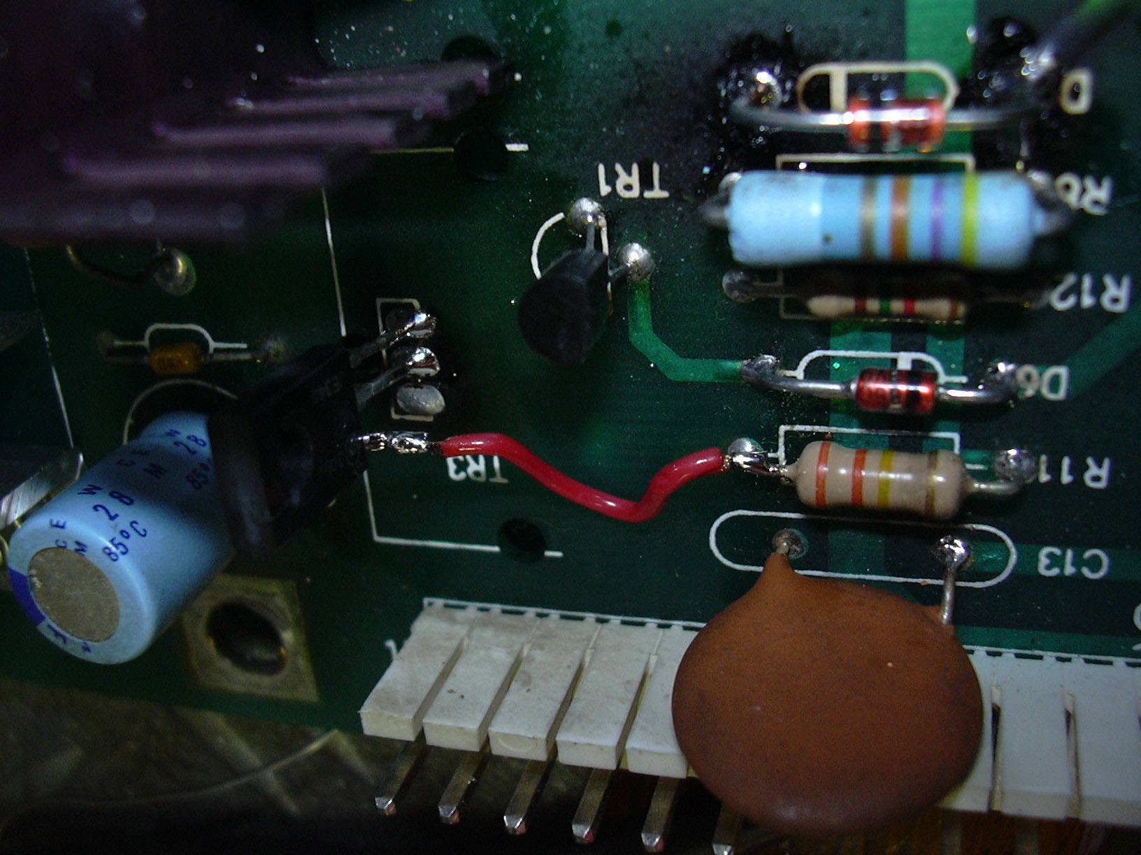
rail of the HV supply. I replaced D6, TR1, TR3 and D9. Unfortunately
after powering back up (off load) the 68V measured +30V again. After
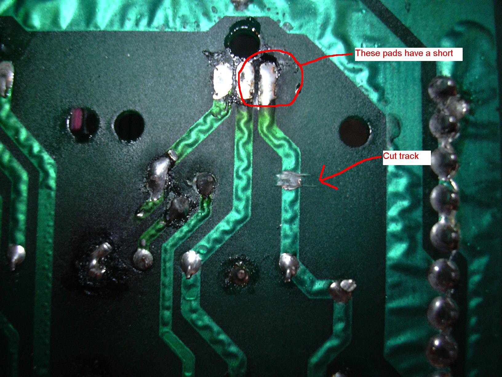
much more testing, with various components out of circuit I found that
I had a low resistance path on the PCB between the collector and
emitter of TR3. This seemed to be due to lots of carbon deposits around
those pads, which would not clean off. The only way to get a reliable
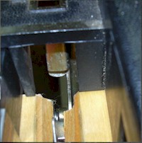
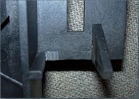
repair was to replace the faulty section of track with a wire link. I
cut the track coming from the emitter of TR3:
and replaced this with a wire link on the
component side of the board directly to the emitter of TR3:
I powered it back up off load, and after
checking the voltages were correct I left it for a couple of hours just
to make sure there was no overheating and all the voltages remained
stable:

Fortunately the display was not damaged, and everything seems to be working OK now.
Heres some more pictures of the machine: